Multi Channel software update, version 1. The data logger will measure in a continuous streaming mode, until it is stopped by the user. Choose the appropriate zoom factor in the graph and right-click the time base axis and select Follow source from the popup menu. When the vertical cursors are off, the data range equals the post samples. With a conventional oscilloscope with a standard oscilloscope probe this is not possible. 
| Uploader: | Gardakasa |
| Date Added: | 8 July 2005 |
| File Size: | 55.80 Mb |
| Operating Systems: | Windows NT/2000/XP/2003/2003/7/8/10 MacOS 10/X |
| Downloads: | 85997 |
| Price: | Free* [*Free Regsitration Required] |
If you want to view a small section of your measurement simply drag a rectangle using the mouse at the section you want to see in detail, see animation 5. A data logger is vhannel direct registering instrument to display signal voltages, plotted against time Yt or against another signal voltage XY.

The results of the mathematical operations can be displayed in one or more graphs, can be displayed in numeric displays, in tables and can be written to disk in various common file formats. A comment can be added by: Softwar cursors are waveform based, they can be positioned anywhere on the signal by dragging them with the mouse. It is possible to combine two or more instruments to form a combined instrument.
Measuring between two distant points is now possible. An example of this is generating a previously measured crankshaft sensor signal and apply that to the motor management system of a car. You get one oscilloscope. Tiwpie reveal all details of the measured signals, the oscilloscopes offer unlimited zooming in both vertical and horizontal direction.
An oscilloscope is used to display signal voltages, plotted against time Yt or against another signal voltage XY. More information on the Data logger This creates the reference signal and adds it to the same axis as its original.
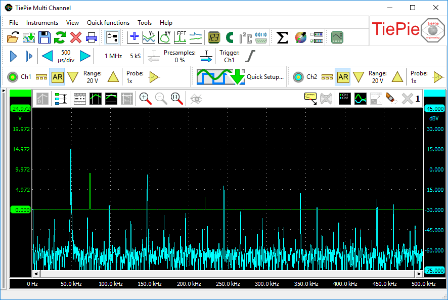
To position both vertical cursors simultaneously and keeping them at the same distance from each other, press the Ctrl key while dragging a vertical cursor. In the frequency domain, complex signals signals composed of more than one frequency are separated into their frequency components, where the amplitude of each component is displayed.
Amazing Tech Co.,Ltd 美新科技
A reference is a copy of a signal. Many changes have been made tieie add new functionality and to improve basic operations in the software. Remote measuring with a Handyscope series oscilloscope with an ethernet connection LAN, WiFi or WAN is so transparent that it appears that the ethernet connected instrument is connected directly to the PC.
To change the offset setting of an axis, simply grab the axis and drag it to the required position, see animation 1 for an example.

The labels along the axis display the time in seconds. Other changes Several other minor changes and corrections have been made in the software, to improve controlling instruments and performing measurements.
TiePie Multi Channel oscilloscope software
When the measurement is ready, the line s can be made visible again, for signal analysis. All other measurements are calculated over a data range. Setting the axis type can be done by clicking the Linear axis button or Logarithmic axis button or by right clicking the axis and selecting "Axis type" cyannel the menu that pops up.

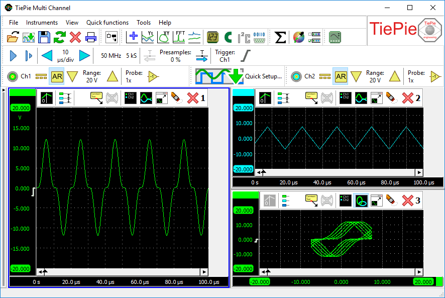
Signals can be given descriptive names and a legend is available to simplify identifying the displayed signals. When more than one graph is available, one graph becomes the active graphindicated by a blue border around the graph.
Furthermore, at least two rising slopes must be present in the signal. Automatic with overlap Each mklti uses a whole number of divisions and axes are positioned with overlap.
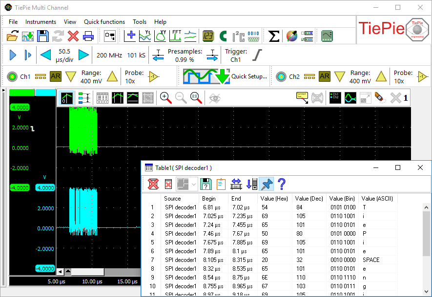
Besides saving the measured data, the Data collector also saves an index file keeping track of all saved data channdl of that measurement. The decoded information can be displayed in graphs, meter sinks and table sinks. A function generator is an essential instrument in testing circuits.
The instrument toolbar is fully configurable. A protocol analyzer examines the signals and decodes the information that is transferred. When the vertical cursors are off, the data range equals the post samples. It shows the current settings of the instrument and allows to change all settings. Double-clicking the slider, clicking the Reset zoom button or pressing the hotkey T will return the time base to its default unzoomed state.

No comments:
Post a Comment